Rotary Encoder Demo And Led Data Counter Using Spartan 3E !!
Bonjour, Comme deuxième phase (Première Phase) dans la découverte de carte FPGA Spartan 3E aujourd'hui je vais essayer de pratiquer deux tests successives.
Rotary Encoder Démonstration:
Commençons tout d'abord par définir le Rotary Encoder, Les codeurs rotatifs sont un type de capteurs permettant de délivrer une information d'angle, en mesurant la rotation effectuée autour d'un axe.
L'information de vitesse peut alors être déduite de la variation de la position par rapport au temps. Plus le codeur rotatif tourne lentement, plus la déduction de vitesse perd en précision.
Il existe 2 principaux types :
- Le codeur rotatif incrémental
- Le codeur rotatif absolu
qui ajoute ou soustrait (selon le sens de rotation) une unité à un compteur à chaque rotation supérieure à la résolution du capteur. Le compteur est généralement remis à zéro lorsque l'appareil est allumé. C'est le cas de la souris d'ordinateur à boule.
qui intègre son propre compteur. Ce genre de capteur est généralement calibré et initialisé une seule fois, et il conserve normalement sa valeur lors de l'arrêt de l'appareil. C'est le cas des compteurs kilométriques des automobiles à la différence du "compteur journalier" qui peut être remis a zéro par l'utilisateur.

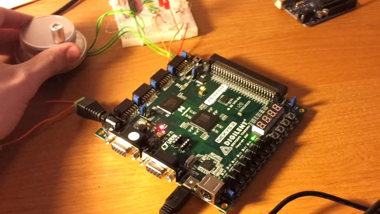
La photo si dessous démontre le fonctionnement de rotary encoder existant dans la carte Spartan 3E, Aujourd'hui on va écrire un simple programme en VHDL démontrant le fonctionnement de cette derniére sur les diodes Leds existants sur la Spartan 3E.
// Rotary Encoder Demo----------------------------------------------------------------------------------
-- Company:
-- Engineer:
--
-- Create Date:    18:27:09 03/24/2016
-- Design Name:
-- Module Name:    rotate_encoder - Behavioral
-- Project Name:
-- Target Devices:
-- Tool versions:
-- Description:
--
-- Dependencies:
--
-- Revision:
-- Revision 0.01 - File Created
-- Additional Comments:
--
----------------------------------------------------------------------------------
----------------------------------------------------------------------------------
library IEEE;
use IEEE.STD_LOGIC_1164.ALL;
use IEEE.NUMERIC_STD.ALL;
library UNISIM;
use UNISIM.VComponents.all;

entity rot_s is
Port ( clk : in STD_LOGIC;
rot_a : in STD_LOGIC;
rot_b : in STD_LOGIC;
rot_center : in STD_LOGIC;
led : out STD_LOGIC_VECTOR (7 downto 0));
end rot_s;

architecture Behavioral of rot_s is

signal rotary_a_in: std_logic;
signal rotary_b_in: std_logic;
signal rotary_q1: std_logic;
signal rotary_q2: std_logic;
signal rotary_in: std_logic_vector(1 downto 0);
signal rotary_event: std_logic;
signal rotary_left:std_logic;
signal delay_rotary_q1:std_logic;
signal center_flag:std_logic;

begin

rotary_a_in <= rot_a;
rotary_b_in <= rot_b;

rotary_filter: process(clk)
begin
if clk'event and clk='1' then
rotary_in <= rotary_b_in & rotary_a_in;

case rotary_in is
when "00" => rotary_q1 <= '0';
rotary_q2 <= rotary_q2;
when "01" => rotary_q1 <= rotary_q1;
rotary_q2 <= '0';
when "10" => rotary_q1 <= rotary_q1;
rotary_q2 <= '1';
when "11" => rotary_q1 <= '1';
rotary_q2 <= rotary_q2;
when others => rotary_q1 <= rotary_q1;
rotary_q2 <= rotary_q2;
end case;
end if;
end process rotary_filter;

direction: process(clk)
begin
if clk'event and clk='1' then

delay_rotary_q1 <= rotary_q1;
if rotary_q1='1' and delay_rotary_q1='0' then
rotary_event <= '1';
rotary_left <= rotary_q2;
else
rotary_event <= '0';
rotary_left <= rotary_left;
end if;
end if;
end process direction;

led_switch: process(clk,rotary_event,rotary_left)

variable i : integer;
variable index : integer;
begin
if clk'event and clk='1' then
if rotary_event='1' and rotary_left='0' then --left
led <="00000000";
i:=i+1;
index :=i mod 8;
led(index)<='1';
end if;
if rotary_event='1' and rotary_left='1' then --right
led <="00000000";
if i=0 then
i:=8;
end if;
i:=i-1;
index :=i mod 8;
led(index)<='1';
end if;
end if;
end process led_switch;

process(rot_center)
begin
if (rot_center='1') then
center_flag<='1';
elsif (rot_center='0') then
center_flag<='0';
end if;
end process;
end Behavioral;
et pour la configuration physique de variables avec la carte
NET "rot_a" LOC = "K18" ;
NET "rot_b" LOC = "G18" ;
NET "rot_center" LOC = "V16";
NET "led<7>" LOC = "F9";
NET "led<6>" LOC = "E9" ;
NET "led<5>" LOC = "D11";
NET "led<4>" LOC = "C11";
NET "led<3>" LOC = "F11";
NET "led<2>" LOC = "E11";
NET "led<1>" LOC = "E12";
NET "led<0>" LOC = "F12";
NET "clk" LOC = "C9";
NET "rot_b" LOC = "G18" ;
NET "rot_center" LOC = "V16";
NET "led<7>" LOC = "F9";
NET "led<6>" LOC = "E9" ;
NET "led<5>" LOC = "D11";
NET "led<4>" LOC = "C11";
NET "led<3>" LOC = "F11";
NET "led<2>" LOC = "E11";
NET "led<1>" LOC = "E12";
NET "led<0>" LOC = "F12";
NET "clk" LOC = "C9";
Led Data Counter
L'autre test réalisé aujourd'hui c'est de réaliser un compteur simple modulo 10 de façon successives, avec un bouton pause et autre bouton reset asynchrone. Donc au bout du programme il faut énoncer qu'un tel compteur sera construit de 4 bascules capables de compter de 0 a 15 et il faut le boucler avec une remise a zéro lorsqu'il dépasse le 9.
// Led Data Counter----------------------------------------------------------------------------------
-- Company: There is no company
-- Engineer: Aymen Lachkhem
--
-- Create Date:    01:27:11 03/24/2016
-- Design Name:
-- Module Name:    counter - Behavioral
-- Project Name:
-- Target Devices:
-- Tool versions:
-- Description:
--
-- Dependencies:
--
-- Revision:
-- Revision 0.01 - File Created
-- Additional Comments:
--
----------------------------------------------------------------------------------
library IEEE;
use IEEE.STD_LOGIC_1164.ALL;
use IEEE.STD_LOGIC_ARITH.ALL;
use IEEE.STD_LOGIC_UNSIGNED.ALL;
entity counter is
port ( clk : in std_logic;
 reset : in std_logic;
 pause : in std_logic;
 count_out : out std_logic_vector(3 downto 0)); -- i m going to select 4 Leds in spartan 3e to show as how
 --bit led counter work
end counter;
architecture Behavioral of counter is
signal temp_count : std_logic_vector(3 downto 0) := x"0";
signal slow_clk : std_logic;
-- Clock divider can be changed to suit application.
-- Clock (clk) is normally 50 MHz, so each clock cycle
-- is 20 ns. A clock divider of 'n' bits will make 1
-- slow_clk cycle equal 2^n clk cycles.
signal clk_divider : std_logic_vector(23 downto 0) := x"000000";
begin
-- Process that makes slow clock go high only when MSB of
-- clk_divider goes high.
clk_division : process (clk, clk_divider)
begin
 if (clk = '1' and clk'event) then
 clk_divider <= clk_divider + 1;
 end if;

 slow_clk <= clk_divider(23);
end process;
counting : process(reset, pause, slow_clk, temp_count)
begin
 if reset = '1' then
 temp_count <= "0000"; -- Asynchronous reset.
 elsif pause = '1' then
 temp_count <= temp_count; -- Asynchronous count pause.
 else

 if slow_clk'event and slow_clk ='1' then -- Counting state
 if temp_count < 9 then
 temp_count <= temp_count + 1; -- Counter increase
 else
 temp_count <= "0000"; -- Rollover to zero
 end if;
 end if;
 end if;
count_out <= temp_count; -- Output
end process;
end Behavioral; -- End module.
et pour la configuration physique de variables avec la carte
NET "clk" LOC = "C9" ;
NET "count_out<0>" LOC = "F12" ; # LED<0>
NET "count_out<1>" LOC = "E12" ; # LED<1>
NET "count_out<2>" LOC = "E11" ; # LED<2>
NET "count_out<3>" LOC = "F11" ; # LED<3>
NET "reset" LOC = "L13" ; # reset
NET "pause" LOC = "L14" ; # LED<3>
NET "count_out<0>" LOC = "F12" ; # LED<0>
NET "count_out<1>" LOC = "E12" ; # LED<1>
NET "count_out<2>" LOC = "E11" ; # LED<2>
NET "count_out<3>" LOC = "F11" ; # LED<3>
NET "reset" LOC = "L13" ; # reset
NET "pause" LOC = "L14" ; # LED<3>

Et comme l'habitude une vidéo démonstrative du fonctionnement:
Have a Good Day :)
Aucun commentaire:
Enregistrer un commentaire