Control Your Own Robot Using Labview
Good morning dears Followers, Today i came with a new idea not far than my last article. I m going to control the same robot but using a different way to command.
In my last article i showed how to control a Robot, Robotic Arm, Electronic system using C# and today i will demonstrate the same idea using one other software more professional in those kind of project which is in fact Labview.
 |
| Main Work |
Like i mentionned in my last article, you have the choice to choose any MCU to make this project since the moment when this one contains UART.
My choice was selected in ATMEGA328, because i have a big part of the program ready from my last article. But even if you want to do this project using PIC or Arduino or STM32. The global fonctionnement is the same.
Let's take a look in our MCU.

This picture show that PIN 2 is the RX PIN and PIN 3 is the TX PIN and those two pin play the external interface given by the UART Module included in ATMEGA328.
So the Global idea of this project is : there is a graphic interface done in Labview who could communicate instantly and directly through serial port with an electronic circuit contains ATMEGA328.
This one every moment he receive a data through his UART module he will convert it to an ordre and give it to L293D Circuits.
L293D Circuits will amplify those ordres and give them to the robot motor.
The electronic circuit resume the idea.

The program that you have to put it in the MCU is:
/*  Control your Robot Using Labview
 *  Project done by : Aymen Lachkhem
 *  Aymenlachkem@gmail.com
 *  Blog site : letselectronic.blogspot.com
 */

void setup() {
         pinMode(A0, OUTPUT);
         pinMode(A1, OUTPUT);
         pinMode(A3, OUTPUT);
         pinMode(A4, OUTPUT);
         pinMode(2, OUTPUT);
         pinMode(3, OUTPUT);
         pinMode(4, OUTPUT);
         pinMode(5, OUTPUT);
         pinMode(6, OUTPUT);
         pinMode(7, OUTPUT);
         pinMode(11, OUTPUT);
         pinMode(12, OUTPUT);
         digitalWrite(A0,LOW);
         digitalWrite(A1,LOW);
         digitalWrite(A3,LOW);
         digitalWrite(A4,LOW);
         digitalWrite(2,LOW);
         digitalWrite(3,LOW);
         digitalWrite(4,LOW);
         digitalWrite(5,LOW);
         digitalWrite(6,LOW);
         digitalWrite(7,LOW);
         digitalWrite(11,LOW);
         digitalWrite(12,LOW);
}

void loop() {
  blinker();
  Serial.begin(9600);
   if (Serial.available() > 0) {
    char a = Serial.read();
if ( a == '4'){robot_left(); }
if ( a == '1'){robot_up();}
if ( a == '3'){robot_right();}
if ( a == '2'){robot_down();}
if ( a == '0'){robot_stop();}
}}

void blinker()
{
  digitalWrite(A3,HIGH);
  digitalWrite(A4,LOW);
  delay(100);
  digitalWrite(A3,LOW);
  digitalWrite(A4,HIGH);
  delay(100);
}
void robot_left()
{
  digitalWrite(A1,HIGH);
  digitalWrite(A0,LOW);
  digitalWrite(2,HIGH);
  digitalWrite(3,LOW);
  digitalWrite(4,LOW);
  digitalWrite(5,HIGH);
  digitalWrite(6,LOW);
  digitalWrite(7,HIGH);
}
void robot_up()
{
  digitalWrite(A1,HIGH);
  digitalWrite(A0,LOW);
  digitalWrite(2,HIGH);
  digitalWrite(3,LOW);
  digitalWrite(4,HIGH);
  digitalWrite(5,LOW);
  digitalWrite(6,HIGH);
  digitalWrite(7,LOW);
}
void robot_right()
{
  digitalWrite(A0,HIGH);
  digitalWrite(A1,LOW);
  digitalWrite(3,HIGH);
  digitalWrite(2,LOW);
  digitalWrite(4,HIGH);
  digitalWrite(5,LOW);
  digitalWrite(6,HIGH);
  digitalWrite(7,LOW);
}
void robot_down()
{
  digitalWrite(A0,HIGH);
  digitalWrite(A1,LOW);
  digitalWrite(3,HIGH);
  digitalWrite(2,LOW);
  digitalWrite(5,HIGH);
  digitalWrite(4,LOW);
  digitalWrite(7,HIGH);
  digitalWrite(6,LOW);
}

void robot_stop()
{
  digitalWrite(A0,LOW);
  digitalWrite(A1,LOW);
  digitalWrite(3,LOW);
  digitalWrite(2,LOW);
  digitalWrite(5,LOW);
  digitalWrite(4,LOW);
  digitalWrite(7,LOW);
  digitalWrite(6,LOW);
}
Now Let's speak about the graphic interface done in Labview.
Before all, For those who dont Know Labview take a look here:
In the official site ni.com they defined Labview like a highly productive development environment for creating custom applications that interact with real-world data or signals in fields such as science and engineering.

LabVIEW itself is a software development environment that contains numerous components, several of which are required for any type of test, measurement, or control application.
One of the best part of labview is the programming way which is totaly graphic, all what the programmer have to do is to collect the block and make tham work together and here an exemple.

In our interface we HAVE to use VISA, so what is VISA ?
In the same officialy site they defined VISA like The Virtual Instrument Software Architecture (VISA) a standard for configuring, programming, and troubleshooting instrumentation systems comprising GPIB, VXI, PXI, Serial, Ethernet, and/or USB interfaces. VISA provides the programming interface between the hardware and development environments such as LabVIEW, LabWindows/CVI, and Measurement Studio for Microsoft Visual Studio. NI-VISA is the National Instruments implementation of the VISA I/O standard. NI-VISA includes software libraries, interactive utilities such as NI I/O Trace and the VISA Interactive Control, and configuration programs through Measurement & Automation Explorer for all your development needs. NI-VISA is standard across the National Instruments product line. With NI-VISA, you can feel confident that your software development will not become obsolete as your instrumentation interface hardware needs evolve into the future.
One of the big part given by VISA is serial configuration.
Like i just said before the main idea of our project is based in serial communication.
So if you want to get it work you have just to be sure that's VISA driver is installed in your computer.
To make your own Graphic interface in Labview you have two panel to build, the design one and the programming one. and here is both of them.
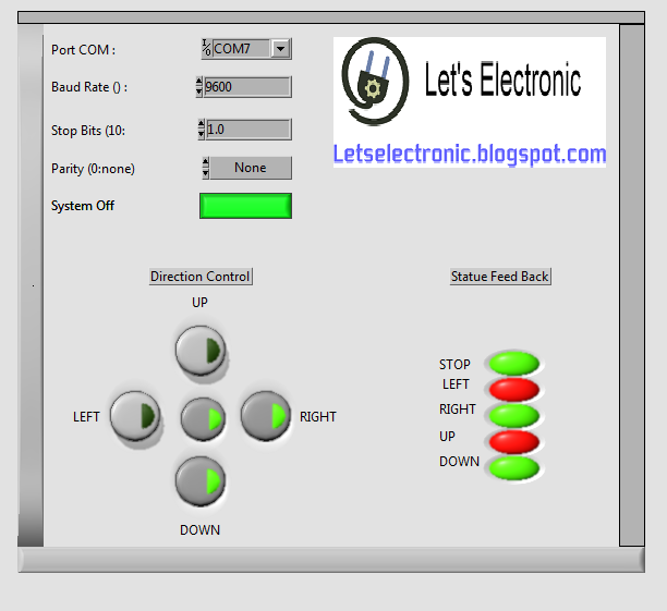

Which make the global work inside Labview look like:

Using A virtuel Serial Port Driver you could test your work between ISIS and Labview and here is a demstrative Video.
And That's it,
Software to Download:
Have a Good Day, See you Soon, Aymen Lachkhem
Let'S Electronic : Control Your Own Robot Using Labview >>>>> Download Now
RépondreSupprimer>>>>> Download Full
Let'S Electronic : Control Your Own Robot Using Labview >>>>> Download LINK
>>>>> Download Now
Let'S Electronic : Control Your Own Robot Using Labview >>>>> Download Full
>>>>> Download LINK