samedi 20 août 2016

Stop Using Proteus ARES ✨ Here Is My EAGLE PCB Tutoriels Step By Step ✨

Stop Using Proteus ARES !! Here is my EAGLE PCB tutoriels

Hello dears followers, Today i came with a new idea completly different of my usually published articles. I m not going to talk about a MCU or a program style. My global idea today is just like it showed in article's title '' let's stop using proteus ARES to make our PCB".


I have been doing a fair bit of PCB design work of late, and I always used to use Proteus for schematic drawing, sometimes simulating and PCB design. So why not to use some other software more professional ? 

The idea was started with me since 3 years ago when i just noted that's there is a sofware named EAGLE Cadsoft more professional than Proteus specialy in making PCB Design.

Résultat de recherche d'images pour "eagle cadsoft"


So Today i m going to show you:
  1.  How to install Eagle Cadsoft, Patch it to make it professional.    
  2.  How to update library in Eagle.
  3.  How to make a simple project (schematic + PCB). 
  4.  How to make a advanced project (Schematic + Layout).
Before that let's just make a little comparison between Proteus and Eagle.


Proteus is an all in one product from schematics to board layout through to simulation on a high level. Eagle is schematics and board layout design software only, no practical simulation . They're very different products. Proteus is used in schools because somehow they've managed to sweetheart a deal for extremely low cost to free licensing on that level in hopes to net students into depending on it for their professional carers. Eagle is used because it uses industry standards, and although not as newbie friendly it is technically full featured, even the free version.


For it's function features and price, Eagle is the only real 'solution' out there. There are many other choices, all which will require a learning curve and design of new libraries for components.

There is a Lot of PCB creating Software, let's be honest and said that the big advantage of Proteus is Simulation part, but my article's title is about making pcb and here we have to be sure all of us that's Eagle is totaly better than Ares in this point.

Here is my graduation project 3 years ago maked using Eagle Cadsoft.


And here is the pcb


I m sure that's in making my PCB in ARES i found more than one problem specially when i search for component, many of them i was forced to created. Also library problem and, i could just in one word said thats ARES is LIMITED front of EAGLE.

Download and installing and patching Eagle.

All what you have to do is to click here to download your eagle professional version. CLICK ME.
A compressed file you will receive in few minutes.

  • Run eagle-win-6.5.0.exe. (same file from official website)
  • Click "Setup" and the installer will start.
  • Run the installation and then select to "Run as Freeware". Installation completes.
  • Start Cadsoft Eagle software. (Select "Run as Freeware" again if asked)

    You will see "Control Panel - EAGLE 6.5.0 Light" as the title of the window.
  • Open Cadsoft Eagle installtion directory and look for 'eagle.exe' (example: C:\Program Files (x86)\EAGLE-6.5.0\bin)
  • Make a copy of "cadsoft.eagle.professional.6.5.0-patch.exe" in the directory in which 'eagle.exe' was found.
  • Run "cadsoft.eagle.professional.6.5.0-patch.exe" as administrator.
  • Click 'Patch' and you're done! You will receive a message in the patch software saying "---PATCHING DONE---"
  • You can now delete "cadsoft.eagle.professional.6.5.0-patch.exe" from the Cadsoft Eagle installation directory.
  • Start Cadsoft Eagle.

    You will see "Control Panel - EAGLE 6.5.0 Professional" as the title of the window.
  
Here is a step by step video of how to download and to install it. Enjoy


Library Using and update.

I just put with my eagle a big library which include a big part of component, so when you open a new project and a new schematic inside it. Just click in Library and Click use and click all library included here:  (example: C:\Program Files (x86)\EAGLE-6.5.0\lbr). That's it.

Make your own simple project in Eagle.

I m going to make the most famous and easy circuit in electronic which is 5V Regulation


The Layout Design will look like:


And here is a step by step Video demonstrate how i did it:


This circuit like he is known give us a regular ready 5V from a 12V.

MAX/RS232 TTL To Serial Interface inside Eagle.

This Circuit is so used in interfacing MCU with external world, many of developpement board just include this one and here the schematic:


The Layout:


And here a video of how i did this circuit and layout step by step.


2 Motor Control with L293D

L293D is Circuit able to control two DC motor with a variation in speed and direction, he is strongly used in robotic world.
here is the schematic :


And here is the Layout: (you could make better i just wanted to show how is easy to use straps)


 Here the video:


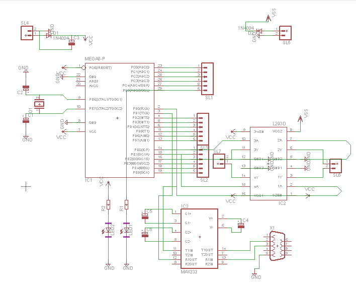
Make an advanced PCB Project inside Eagle.


This is the advanced project thats i m going to do. In fact it include  an ATMEGA MCU, a connectors for all his digital pins, and a max232/rs232 interface, a motor control based in l293D so we could just said thats we are making a developpement board for our MCU.

and like always here a long video demonstrate how i did that.

Schematic

Layout


And here the video


See you soon, AYMEN LACHKHEM     

mardi 16 août 2016

Control Your Own Robot Using Labview

Control Your Own Robot Using Labview

Good morning dears Followers, Today i came with a new idea not far than my last article. I m going to control the same robot but using a different way to command. 
In my last article i showed how to control a Robot, Robotic Arm, Electronic system using C# and today i will demonstrate the same idea using one other software more professional in those kind of project which is in fact Labview.


Main Work

Like i mentionned in my last article, you have the choice to choose any MCU to make this project since the moment when this one contains UART.
My choice was selected in ATMEGA328, because i have a big part of the program ready from my last article. But even if you want to do this project using PIC or Arduino or STM32. The global fonctionnement is the same.

Let's take a look in our MCU.

This picture show that PIN 2 is the RX PIN and PIN 3 is the TX PIN and those two pin play the external interface given by the UART Module included in ATMEGA328.

So the Global idea of this project is : there is a graphic interface done in Labview who could communicate instantly and directly through serial port with an electronic circuit contains ATMEGA328.

This one every moment he receive  a data through his UART module he will convert it to an ordre and give it to L293D Circuits.
L293D Circuits will amplify those ordres and give them to the robot motor.

The electronic circuit resume the idea.


The program that you have to put it in the MCU is:


/*  Control your Robot Using Labview 
 *  Project done by : Aymen Lachkhem
 *  Aymenlachkem@gmail.com
 *  Blog site : letselectronic.blogspot.com
 */

void setup() {
         pinMode(A0, OUTPUT);
         pinMode(A1, OUTPUT);
         pinMode(A3, OUTPUT);
         pinMode(A4, OUTPUT);
         pinMode(2, OUTPUT);
         pinMode(3, OUTPUT);
         pinMode(4, OUTPUT);
         pinMode(5, OUTPUT);
         pinMode(6, OUTPUT);
         pinMode(7, OUTPUT);         
         pinMode(11, OUTPUT);
         pinMode(12, OUTPUT);
         digitalWrite(A0,LOW);
         digitalWrite(A1,LOW);
         digitalWrite(A3,LOW);
         digitalWrite(A4,LOW);
         digitalWrite(2,LOW);
         digitalWrite(3,LOW);
         digitalWrite(4,LOW);
         digitalWrite(5,LOW);
         digitalWrite(6,LOW);
         digitalWrite(7,LOW);
         digitalWrite(11,LOW);
         digitalWrite(12,LOW);
}

void loop() {       
  blinker();
  Serial.begin(9600);  
   if (Serial.available() > 0) {
    char a = Serial.read();
if ( a == '4'){robot_left(); }  
if ( a == '1'){robot_up();}
if ( a == '3'){robot_right();}
if ( a == '2'){robot_down();}
if ( a == '0'){robot_stop();}
}}

void blinker()
{ 
  digitalWrite(A3,HIGH);
  digitalWrite(A4,LOW);
  delay(100);
  digitalWrite(A3,LOW);
  digitalWrite(A4,HIGH);
  delay(100);
}  
void robot_left()
{
  digitalWrite(A1,HIGH);
  digitalWrite(A0,LOW);
  digitalWrite(2,HIGH);
  digitalWrite(3,LOW);
  digitalWrite(4,LOW);
  digitalWrite(5,HIGH);
  digitalWrite(6,LOW);
  digitalWrite(7,HIGH);
}
void robot_up()
{
  digitalWrite(A1,HIGH);
  digitalWrite(A0,LOW);
  digitalWrite(2,HIGH);
  digitalWrite(3,LOW);
  digitalWrite(4,HIGH);
  digitalWrite(5,LOW);
  digitalWrite(6,HIGH);
  digitalWrite(7,LOW);  
}  
void robot_right()
{
  digitalWrite(A0,HIGH);
  digitalWrite(A1,LOW);
  digitalWrite(3,HIGH);
  digitalWrite(2,LOW);
  digitalWrite(4,HIGH);
  digitalWrite(5,LOW);
  digitalWrite(6,HIGH);
  digitalWrite(7,LOW);  
}
void robot_down()
{
  digitalWrite(A0,HIGH);
  digitalWrite(A1,LOW);
  digitalWrite(3,HIGH);
  digitalWrite(2,LOW);
  digitalWrite(5,HIGH);
  digitalWrite(4,LOW);
  digitalWrite(7,HIGH);
  digitalWrite(6,LOW);  
}

void robot_stop()
{
  digitalWrite(A0,LOW);
  digitalWrite(A1,LOW);
  digitalWrite(3,LOW);
  digitalWrite(2,LOW);
  digitalWrite(5,LOW);
  digitalWrite(4,LOW);
  digitalWrite(7,LOW);
  digitalWrite(6,LOW);  
}

Now Let's speak about the graphic interface done in Labview.
Before all, For those who dont Know Labview take a look here:
In the official site ni.com they defined Labview like a highly productive development environment for creating custom applications that interact with real-world data or signals in fields such as science and engineering.


LabVIEW itself is a software development environment that contains numerous components, several of which are required for any type of test, measurement, or control application.

One of the best part of labview is the programming way which is totaly graphic, all what the programmer have to do is to collect the block and make tham work together and here an exemple.


In our interface we HAVE to use VISA, so what is VISA ?

In the same officialy site they defined VISA like The Virtual Instrument Software Architecture (VISA)  a standard for configuring, programming, and troubleshooting instrumentation systems comprising GPIB, VXI, PXI, Serial, Ethernet, and/or USB interfaces. VISA provides the programming interface between the hardware and development environments such as LabVIEW, LabWindows/CVI, and Measurement Studio for Microsoft Visual Studio. NI-VISA is the National Instruments implementation of the VISA I/O standard. NI-VISA includes software libraries, interactive utilities such as NI I/O Trace and the VISA Interactive Control, and configuration programs through Measurement & Automation Explorer for all your development needs. NI-VISA is standard across the National Instruments product line. With NI-VISA, you can feel confident that your software development will not become obsolete as your instrumentation interface hardware needs evolve into the future.

Résultat de recherche d'images pour "visa labview"

One of the big part given by VISA is serial configuration.
Like i just said before the main idea of our project is based in serial communication.
So if you want to get it work you have just to be sure that's VISA driver is installed in your computer.

To make your own Graphic interface in Labview you have two panel to build, the design one and the programming one. and here is both of them.


Which make the global work inside Labview look like:


Using A virtuel Serial Port Driver you could test your work between ISIS and Labview and here is a demstrative Video.


And That's it, 


Software to Download:


Have a Good Day, See you Soon, Aymen Lachkhem


jeudi 11 août 2016

Automatic Wirless Voltage Acquisation

Wirless Voltage Acquisation

Dears Followers, Today i m coming with a new project based in Wirless Communication, As it is written in  the article's title i m going to follow instantly the voltage level in some where so far from where I m.


The idea was given to me by one of my best friend who ask me how he could know the voltage level in some where far from him, Which protocol he have to know and which electronic component he have to use to do those kind of project.

In fact, the idea is simple and easy based in UART protocol. The MCU that's i m going to use is the same ATMEGA 328p.
I have to make a double circuit, the first one is for sure the transmitter and the second is the receiver.


Like i said i m going to use ATMEGA 328p, the same way to communicate will be available if you are going to use one other MCU for exemple PIC, you have just to check thats he contains UART.   


Résultat de recherche d'images pour "atmega328"
ATMEGA 328p PINOUT
To make a wirless intelligent work we must use two MCU. One for the first circuit and the other for the receiver circuit.
The electronic component thats i m going to use is Xbee Pro. In those kind of projects (wirless) you could use Bluetooth or RF433 MHz but because the distance commanded and how much it is easy to interface it i m going to use Xbee.

Afficher l'image d'origine
Xbee Pro

Every circuit in this project will contains Xbee pro and ATMEGA 328p.

Let's start by the transmitter circuit:

In this circuit, We have to acquisate a voltage between 0 and 125V DC. Like we all know our MCU could only read a voltage between 0V and 5V. So the solution is to add a voltage devider able to convert 125V to 5V.


The rest is easy. We have just to use the adc module in our MCU and for that i put the output of the voltage devider in ADC0 (pin23).


If the test is validate with hyper terminal in Proteus ISIS you have to replace the hyper terminal by Xbee in reality.
Xbee work with 3.3 V so we have to add somes components to adapt it to the MCU.


The circuit is done, we have to add the program of the transmitter and here is it.
/*  Wirless Voltage Acquisation
 *  Project done by : Aymen Lachkhem
 *  Aymenlachkem@gmail.com
 *  Blog site : letselectronic.blogspot.com
 */
float voltage = 0;

void setup() {
  // put your setup code here, to run once:
pinMode(A0,INPUT);
pinMode(0,INPUT);
pinMode(1,OUTPUT);
Serial.begin(9600);

}

void loop() {
  // put your main code here, to run repeatedly:

 voltage = analogRead(A0);
float realvoltage = (voltage * 125) /1023;
delay(100);
Serial.print("VOLTAGE = ");
Serial.print(realvoltage);
Serial.print(" V");
Serial.println();
delay(100);}


Speaking now about the receiver circuit.

In fact, we have a xbee who will read instantly the voltage level, An MCU who will convert this level and make treatement and show it in 2X16 LCD module.

Here is the Circuit to make
  
Replace the COMPIM by the receiver xbee and put this program inside the receiver MCU.


/*  Wirless Voltage Acquisation
 *  Project done by : Aymen Lachkhem
 *  Aymenlachkem@gmail.com
 *  Blog site : letselectronic.blogspot.com
 */
// include the library code:
#include <LiquidCrystal.h>

// initialize the library with the numbers of the interface pins
LiquidCrystal lcd(12, 11, 5, 4, 3, 2);

void setup() {
  // set up the LCD's number of columns and rows:
  lcd.begin(16, 2);
  lcd.print("Wirless Voltage");
  lcd.println("Acquisation");
  delay(1000);
  // initialize the serial communications:
  Serial.begin(9600);
}

void loop() {
  // when characters arrive over the serial port...
  if (Serial.available()) {
    // wait a bit for the entire message to arrive
     delay(100);
    // clear the screen
    lcd.clear();
    // read all the available characters
    while (Serial.available() > 0) {
      // display each character to the LCD
      lcd.write(Serial.read());
    }
  }
}


And Thats it, all what we have to do is to run the transmitter circuit and the receiver one,  and to enjoy the work.


Dont forget to configure the Xbee's before make it work and here a good video showing how to do it.


Like it is demonstrated in this video, to configure 2 Xbee in reason to make the first the transmitter and the second the receiver we have to use X-CTU Software. Clik in the picture to download it.

Afficher l'image d'origine


If you want to make the displaying better, you could easly make your own Software using C# or Visual Basic or Labview.
I recommand Labview to do this because easly he can draw the voltage level in histogramme or in fonction of time.

Afficher l'image d'origine


                                                                    See you Soon AYMEN LACHKHEM

lundi 8 août 2016

How To Make Your Own Robot Controlled With C#, Followed By A WebCam.

How To Make Your Own Robot Controlled With C#, Followed By A WebCam. 

Hello my dears followers, Like it is mentionned in the article title. Today i m going to demonstrate how we could make an intelligent robot, Controlled by your own C# application made in Visual Studio 2012, Followed by a WebCam.


To Make a full project like this one you have many choices to choose. 
The Hard part of this project is done using an Atmega 328p like a principal MCU. You could use any other MCU, For exemple A PIC like PIC16F877 is able also to replace the Atmega328p.
We know that the principal MCU based on the Arduino UNO is ATmega328 so You Could also use Arduino to get the robot working.

ATmega 328p pins 


Those Kind of project based essentially an serial communication. so you have just to use a MCU able to support UART.
There is a step in my project based in PWM so the MCU used have to support PWM also.
And for those how dont know what that means UART and PWM they have just to take a look here:

I choosed directly the ATmega 328p because this one is easier in programming and cheap in price. 
Résultat de recherche d'images pour "atmega328"
ATmega 328p


The robot move in 4 directions using a 4 simple DC motors, and those motors are controlled by 2 L293D.
The camera is just placed in the first servomotor. and this one is place in other one to get sure that the position where the camera is putted could  cover every point. 
Résultat de recherche d'images pour "servo motor web cam"
Placing the WebCam

I showed in this article programming ATmega like an Arduino how to program an ATmega32p like programming a simple arduino. this solution is used today also and this is the full program placed in the MCU memory to make the robot moving.


/*  Control and follow your robot using c# application and webcam 
 *  Project done by : Aymen Lachkhem
 *  Aymenlachkem@gmail.com
 *  Blog site : letselectronic.blogspot.com
 */
#include <Servo.h>
Servo myservo1;
Servo myservo2;
void setup() {
         pinMode(A0, OUTPUT);
         pinMode(A1, OUTPUT);
         pinMode(A3, OUTPUT);
         pinMode(A4, OUTPUT);
         pinMode(2, OUTPUT);
         pinMode(3, OUTPUT);
         pinMode(4, OUTPUT);
         pinMode(5, OUTPUT);
         pinMode(6, OUTPUT);
         pinMode(7, OUTPUT);         
         pinMode(11, OUTPUT);
         pinMode(12, OUTPUT);
         digitalWrite(A0,LOW);
         digitalWrite(A1,LOW);
         digitalWrite(A3,LOW);
         digitalWrite(A4,LOW);
         digitalWrite(2,LOW);
         digitalWrite(3,LOW);
         digitalWrite(4,LOW);
         digitalWrite(5,LOW);
         digitalWrite(6,LOW);
         digitalWrite(7,LOW);
         digitalWrite(11,LOW);
         digitalWrite(12,LOW);
           myservo1.attach(9);
           myservo2.attach(10);
            int i1 = 0;
            int i2 = 90;
         myservo1.write(i1);
         myservo2.write(i2);
}

void loop() {       
  blinker();
  Serial.begin(9600);  
   if (Serial.available() > 0) {
    char a = Serial.read();
if ( a == '1'){robot_left(); }  
if ( a == '2'){robot_up();}
if ( a == '3'){robot_right();}
if ( a == '4'){robot_down();}
if ( a == '5'){camera2_down();}
if ( a == '6'){camera1_up();}
if ( a == '7'){camera2_up();}
if ( a == '8'){camera1_down();}
}}
void blinker()
{ 
  digitalWrite(A3,HIGH);
  digitalWrite(A4,LOW);
  delay(100);
  digitalWrite(A3,LOW);
  digitalWrite(A4,HIGH);
  delay(100);
}  
void robot_left()
{
  digitalWrite(A1,HIGH);
  digitalWrite(A0,LOW);
  digitalWrite(2,HIGH);
  digitalWrite(3,LOW);
  digitalWrite(4,LOW);
  digitalWrite(5,HIGH);
  digitalWrite(6,LOW);
  digitalWrite(7,HIGH);
}
void robot_up()
{
  digitalWrite(A1,HIGH);
  digitalWrite(A0,LOW);
  digitalWrite(2,HIGH);
  digitalWrite(3,LOW);
  digitalWrite(4,HIGH);
  digitalWrite(5,LOW);
  digitalWrite(6,HIGH);
  digitalWrite(7,LOW);  
}  
void robot_right()
{
  digitalWrite(A0,HIGH);
  digitalWrite(A1,LOW);
  digitalWrite(3,HIGH);
  digitalWrite(2,LOW);
  digitalWrite(4,HIGH);
  digitalWrite(5,LOW);
  digitalWrite(6,HIGH);
  digitalWrite(7,LOW);  
}
void robot_down()
{
  digitalWrite(A0,HIGH);
  digitalWrite(A1,LOW);
  digitalWrite(3,HIGH);
  digitalWrite(2,LOW);
  digitalWrite(5,HIGH);
  digitalWrite(4,LOW);
  digitalWrite(7,HIGH);
  digitalWrite(6,LOW);  
}

void camera2_down()
{
  int i3 = myservo2.read();
  myservo2.write(i3 - 1);
}
void camera2_up()
{
  int i4 = myservo2.read();
  myservo2.write(i4 + 1);
}
void camera1_down()
{
  int i5 = myservo1.read();
  myservo1.write(i5 - 1);
}
void camera1_up()
{
  int i6 = myservo1.read();
  myservo1.write(i6 + 1);
}


This is The Complet Circuit that you have to draw.

Full Circuit


The Hard part of the project is just done so let's talk about the soft part.
We have here to build an Application based in serial communication able to connect directly the robot.
There is many solution to do this, for exemple Labview is one of the best interfacing system also Visual Basic or C#.
I  used C# to do this. A simple application in one only panel with a serial communication platform.
Many Buttons to control the robot and the camera.


How The Application Work ?

This is simple, We have just to add a serial platform to the app. This one will always ask for the port com and the baud rate. Since the moment your choose your serial parametres the fonctionnemnet of buttons starts. 
Every button you will click will send a code to the MCU and exactly like this that's working.

Résultat de recherche d'images pour "serial communication"


How the WebCam Works ?

In fact, there is a direct library you have to add to your visual studio named AFroge.net Direct Download. After adding this one to your visual studio you have to add this two reference to your project.


The rest is easy, you have just to give the application the permission to look for webcam devices plug in your computer, starts showing what she see, Capture button to save directly the view.

This is the full program written with C# in Visual Studio 2012.

/* Robot controlled by C# , Follewed by a Webcam
Letselectronic.blogspot.com
aymenlachkem@gmail.com
*/
using System;
using System.Collections.Generic;
using System.ComponentModel;
using System.Data;
using System.Drawing;
using System.Linq;
using System.Text;
using System.Threading.Tasks;
using System.Windows.Forms;
using AForge.Video.DirectShow;
using System.IO.Ports;
using System.Diagnostics;


namespace Camera_Project_Lachkhem
{
    public partial class Form1 : Form
    {
        VideoCaptureDevice capture;

        public Form1()
        {
            InitializeComponent();
            getAvailablePorts();


            FilterInfoCollection info = new FilterInfoCollection(FilterCategory.VideoInputDevice);
            if (info != null)
            {
                capture = new VideoCaptureDevice(info[0].MonikerString);
                capture.NewFrame += (s, e) => pictureBox1.Image = (Bitmap)e.Frame.Clone();
                capture.Start();
            }
        }
        void getAvailablePorts()
        {
            string[] Ports = SerialPort.GetPortNames();
            portcom.Items.AddRange(Ports);
        }
        private void button1_Click(object sender, EventArgs e)
        {
            pictureBox1.Image.Save("snapchot.png", System.Drawing.Imaging.ImageFormat.Png);
        }
        protected override void OnClosed(EventArgs e)
        {
            base.OnClosed(e);
            if (capture != null && capture.IsRunning)
            {
                capture.SignalToStop();
                capture = null;

            }

        }

        private void button2_Click(object sender, EventArgs e)
        {
            Close();
        }

        private void dateTimePicker1_ValueChanged(object sender, EventArgs e)
        {

        }

        private void label5_Click(object sender, EventArgs e)
        {

        }

        private void connecter_Click(object sender, EventArgs e)
        {
            {
                try
                {
                    if (portcom.Text == "" || baudrate.Text == "")
                    {
                        textbox1.Text = "Please select port setting ? ";
                    }
                    else
                    {

                        serialPort1.PortName = portcom.Text;
                        serialPort1.BaudRate = Convert.ToInt32(baudrate.Text);
                        progressBar1.Value = 100;
                        textbox1.Text = "Connected";


                    }
                }
                catch (UnauthorizedAccessException)
                {
                    baudrate.Text = "Unauthorized Access";
                }
            }
        }

        private void button3_Click(object sender, EventArgs e)
        {
            serialPort1.Close();
            progressBar1.Value = 0;
        }

        private void Contact_Me_Click(object sender, EventArgs e)
        {
            ProcessStartInfo startInfo = new ProcessStartInfo("iexplore.exe", "http://https://letselectronic.blogspot.com/p/blog-page.html/");
            Process.Start(startInfo);
        }

        private void Visit_My_Blog_Click(object sender, EventArgs e)
        {
            ProcessStartInfo startInfo = new ProcessStartInfo("iexplore.exe", "http://https://letselectronic.blogspot.com/p/blog-page.html/");
            Process.Start(startInfo);
        }

        private void button12_Click(object sender, EventArgs e)
        {
            var myLines = new List<string>();

            myLines.Add("Hello, This Windows application give their Users the ability to control serially or with wirless communication a Robot Followed By a WebCam.");
            myLines.Add("- The MCU used is The high-performance Atmel 8-bit AVR RISC-based microcontroller ATmega 328 ");
            myLines.Add("- The Control Application was made in Visual Studio 2012, written using C# ");
            

            myLines.Add("----------------------------------------- Blog: Letselectronic.blogspot.com ----------------------------------------------------------------------");
            myLines.Add("----------------------------------------- Contact: Aymenlachkem@gmail.com ------------------------------------------------------------------");

            textBox2.Lines = myLines.ToArray();
        }

        private void button7_Click(object sender, EventArgs e)
        {
            serialPort1.Open();
            serialPort1.Write("1");
            serialPort1.Close();
        }

        private void button5_Click(object sender, EventArgs e)
        {
            serialPort1.Open();
            serialPort1.Write("2");
            serialPort1.Close();
        }

        private void button8_Click(object sender, EventArgs e)
        {
            serialPort1.Open();
            serialPort1.Write("3");
            serialPort1.Close();
        }

        private void button6_Click(object sender, EventArgs e)
        {
            serialPort1.Open();
            serialPort1.Write("4");
            serialPort1.Close();
        }

        private void button11_Click(object sender, EventArgs e)
        {
            serialPort1.Open();
            serialPort1.Write("6");
            serialPort1.Close();
        }

        private void button4_Click(object sender, EventArgs e)
        {
            serialPort1.Open();
            serialPort1.Write("5");
            serialPort1.Close();
        }

        private void button9_Click(object sender, EventArgs e)
        {
            serialPort1.Open();
            serialPort1.Write("7");
            serialPort1.Close();
        }

        private void button10_Click(object sender, EventArgs e)
        {
            serialPort1.Open();
            serialPort1.Write("8");
            serialPort1.Close();
        }

        private void turn_on_Click(object sender, EventArgs e)
        {
            serialPort1.Open();
            serialPort1.Write("9");
            serialPort1.Close();
        }

        private void turn_off_Click(object sender, EventArgs e)
        {
            serialPort1.Open();
            serialPort1.Write("a");
            serialPort1.Close();
        }
    }
}


Built your application, Get your file.exe and the Setup. Like always this is a video for more details.

I have all files of this project collected in compressed directory so just contact me to have your free files.


                                                                 See you Soon AYMEN LACHKHEM