Wirless Voltage Acquisation
Dears Followers, Today i m coming with a new project based in Wirless Communication, As it is written in the article's title i m going to follow instantly the voltage level in some where so far from where I m.

The idea was given to me by one of my best friend who ask me how he could know the voltage level in some where far from him, Which protocol he have to know and which electronic component he have to use to do those kind of project.
In fact, the idea is simple and easy based in UART protocol. The MCU that's i m going to use is the same ATMEGA 328p.
I have to make a double circuit, the first one is for sure the transmitter and the second is the receiver.
Like i said i m going to use ATMEGA 328p, the same way to communicate will be available if you are going to use one other MCU for exemple PIC, you have just to check thats he contains UART.


Dont forget to configure the Xbee's before make it work and here a good video showing how to do it.

I have to make a double circuit, the first one is for sure the transmitter and the second is the receiver.
Like i said i m going to use ATMEGA 328p, the same way to communicate will be available if you are going to use one other MCU for exemple PIC, you have just to check thats he contains UART.
| ATMEGA 328p PINOUT |
To make a wirless intelligent work we must use two MCU. One for the first circuit and the other for the receiver circuit.
The electronic component thats i m going to use is Xbee Pro. In those kind of projects (wirless) you could use Bluetooth or RF433 MHz but because the distance commanded and how much it is easy to interface it i m going to use Xbee.
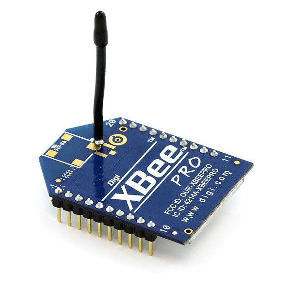 |
| Xbee Pro |
Every circuit in this project will contains Xbee pro and ATMEGA 328p.
Let's start by the transmitter circuit:
In this circuit, We have to acquisate a voltage between 0 and 125V DC. Like we all know our MCU could only read a voltage between 0V and 5V. So the solution is to add a voltage devider able to convert 125V to 5V.

The rest is easy. We have just to use the adc module in our MCU and for that i put the output of the voltage devider in ADC0 (pin23).

If the test is validate with hyper terminal in Proteus ISIS you have to replace the hyper terminal by Xbee in reality.
Xbee work with 3.3 V so we have to add somes components to adapt it to the MCU.

The circuit is done, we have to add the program of the transmitter and here is it.
/*  Wirless Voltage Acquisation
 *  Project done by : Aymen Lachkhem
 *  Aymenlachkem@gmail.com
 *  Blog site : letselectronic.blogspot.com
 */
float voltage = 0;

void setup() {
  // put your setup code here, to run once:
pinMode(A0,INPUT);
pinMode(0,INPUT);
pinMode(1,OUTPUT);
Serial.begin(9600);

}

void loop() {
  // put your main code here, to run repeatedly:

 voltage = analogRead(A0);
float realvoltage = (voltage * 125) /1023;
delay(100);
Serial.print("VOLTAGE = ");
Serial.print(realvoltage);
Serial.print(" V");
Serial.println();
delay(100);}
Speaking now about the receiver circuit.
In fact, we have a xbee who will read instantly the voltage level, An MCU who will convert this level and make treatement and show it in 2X16 LCD module.
Here is the Circuit to make

Replace the COMPIM by the receiver xbee and put this program inside the receiver MCU.
/*  Wirless Voltage Acquisation
 *  Project done by : Aymen Lachkhem
 *  Aymenlachkem@gmail.com
 *  Blog site : letselectronic.blogspot.com
 */
// include the library code:
#include <LiquidCrystal.h>

// initialize the library with the numbers of the interface pins
LiquidCrystal lcd(12, 11, 5, 4, 3, 2);

void setup() {
  // set up the LCD's number of columns and rows:
  lcd.begin(16, 2);
  lcd.print("Wirless Voltage");
  lcd.println("Acquisation");
  delay(1000);
  // initialize the serial communications:
  Serial.begin(9600);
}

void loop() {
  // when characters arrive over the serial port...
  if (Serial.available()) {
    // wait a bit for the entire message to arrive
     delay(100);
    // clear the screen
    lcd.clear();
    // read all the available characters
    while (Serial.available() > 0) {
      // display each character to the LCD
      lcd.write(Serial.read());
    }
  }
}
And Thats it, all what we have to do is to run the transmitter circuit and the receiver one, and to enjoy the work.
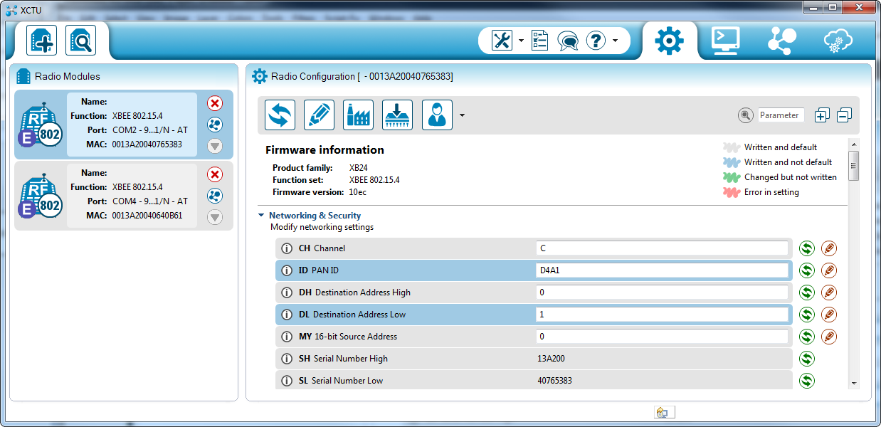
Dont forget to configure the Xbee's before make it work and here a good video showing how to do it.
Like it is demonstrated in this video, to configure 2 Xbee in reason to make the first the transmitter and the second the receiver we have to use X-CTU Software. Clik in the picture to download it.
If you want to make the displaying better, you could easly make your own Software using C# or Visual Basic or Labview.
I recommand Labview to do this because easly he can draw the voltage level in histogramme or in fonction of time.
See you Soon AYMEN LACHKHEM
Aucun commentaire:
Enregistrer un commentaire