Let's get PWM Using Spartan 3E
Dans la meme série de tutoriels que j'ai fait au but de la découverte de technologie FPGA et en particulier la carte Spartan 3E, Aujourd'hui je vais vous montrer comment on fait pour generer un signal PWM (pulse widh modulation), vous expliquer les étapes de programmation que j'ai fait en passant par un test pratique démonstratif.

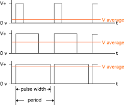
La modulation de largeur d'impulsions (MLI ; en anglais : Pulse Width Modulation, soit PWM), est une technique couramment utilisée pour synthétiser des signaux continus à l'aide de circuits à fonctionnement tout ou rien, ou plus généralement à états discrets.
Le principe général est qu'en appliquant une succession d'états discrets pendant des durées bien choisies, on peut obtenir en moyenne sur une certaine durée n'importe quelle valeur intermédiaire.
Ce phénomène est fortement recommandé pour assurer la variation de vitesse de moteur a courant continu, aujourd'hui je vais vous démontrer comment on peut générer un signal PWM d'une carte FPGA Spartan 3E et visualiser son présence sur des diodes LEDs.

Passons maintenant au programmation;
Voici le programme du projet :
PWM Top Code :---------------------------------------------------------------------------------- -- Company: There is no company -- Engineer: Aymen Lachkhem -- -- Create Date: 02:27:11 03/27/2016 -- Design Name: -- Module Name: counter - Behavioral -- Project Name: -- Target Devices: -- Tool versions: -- Description: -- -- Dependencies: -- -- Revision: -- Revision 0.01 - File Created -- Additional Comments: -- ---------------------------------------------------------------------------------- library IEEE; use IEEE.STD_LOGIC_1164.ALL; use IEEE.STD_LOGIC_ARITH.ALL; use IEEE.STD_LOGIC_UNSIGNED.ALL; entity top is Port ( clk : in std_logic; pwm_out : out std_logic; rotary_a : in std_logic; rotary_b : in std_logic );end top; architecture Behavioral of top is component pwm port( clk: in std_logic; pwm_var: in std_logic_vector(7 downto 0); pwm_out: out std_logic); end component; component rotary port( pwm_var : out std_logic_vector(7 downto 0); rotary_a : in std_logic; rotary_b : in std_logic; clk : in std_logic); end component; signal pwm_var: std_logic_vector (7 downto 0); begin U1 : pwm port map( clk => clk, pwm_var=>pwm_var, pwm_out=>pwm_out ); U2 : rotary port map( pwm_var=>pwm_var, rotary_a=>rotary_a, rotary_b=>rotary_b, clk =>clk ); end Behavioral;
Pour les configurations physiques de mon programme avec la carte Spartan 3E j'ai choisis ces entrées sorties:
NET "clk" PERIOD = 20.0ns HIGH 50%;
NET "clk" LOC = "C9" | IOSTANDARD = LVTTL;
NET "rotary_a" LOC = "K18" | IOSTANDARD = LVTTL | PULLUP;
NET "rotary_b" LOC = "G18" | IOSTANDARD = LVTTL | PULLUP;
NET "pwm_out" LOC = "D5" | IOSTANDARD = LVTTL | SLEW = SLOW | DRIVE = 6 ;
Le programme TOP il inclus deux component que j'ai écris en VHDL aussi :
PWM Code :---------------------------------------------------------------------------------- -- Company: There is no company -- Engineer: Aymen Lachkhem -- -- Create Date: 02:27:00 03/27/2016 -- Design Name: -- Module Name: counter - Behavioral -- Project Name: -- Target Devices: -- Tool versions: -- Description: -- -- Dependencies: -- -- Revision: -- Revision 0.01 - File Created -- Additional Comments: -- ---------------------------------------------------------------------------------- library IEEE; use IEEE.STD_LOGIC_1164.ALL; use ieee.numeric_std.all; entity pwm is port( clk: in std_logic; pwm_var: in std_logic_vector(7 downto 0); pwm_out: out std_logic ); end pwm; architecture Behavioral of pwm is signal counter: std_logic_vector(7 downto 0):="00000000"; signal max_counter: std_logic_vector(7 downto 0):="11111111"; begin process(clk) begin if rising_edge(clk) then counter <= std_logic_vector( unsigned(counter) + 1 ); if counter=max_counter then counter<="00000000"; else if counter<pwm_var then pwm_out<='1'; else pwm_out<='0'; end if; end if; end if; end process; end Behavioral;
Et
ROTARY ENCODER Code :---------------------------------------------------------------------------------- -- Company: There is no company -- Engineer: Aymen Lachkhem -- -- Create Date: 02:24:42 03/27/2016 -- Design Name: -- Module Name: counter - Behavioral -- Project Name: -- Target Devices: -- Tool versions: -- Description: -- -- Dependencies: -- -- Revision: -- Revision 0.01 - File Created -- Additional Comments: -- ---------------------------------------------------------------------------------- library IEEE; use IEEE.STD_LOGIC_1164.ALL; use IEEE.STD_LOGIC_ARITH.ALL; use IEEE.STD_LOGIC_UNSIGNED.ALL; entity rotary is Port ( pwm_var : out std_logic_vector(7 downto 0); rotary_a : in std_logic; rotary_b : in std_logic; clk : in std_logic );end rotary; architecture Behavioral of rotary is signal rotary_a_in : std_logic; signal rotary_b_in : std_logic; signal rotary_in : std_logic_vector(1 downto 0); signal rotary_q1 : std_logic; signal rotary_q2 : std_logic; signal delay_rotary_q1 : std_logic; signal rotary_event : std_logic; signal rotary_left : std_logic; signal led_pattern : std_logic_vector(7 downto 0):= "00000000"; begin rotary_filter: process(clk) begin if clk'event and clk='1' then rotary_a_in <= rotary_a; rotary_b_in <= rotary_b; rotary_in <= rotary_b_in & rotary_a_in; case rotary_in is when "00" => rotary_q1 <= '0'; rotary_q2 <= rotary_q2; when "01" => rotary_q1 <= rotary_q1; rotary_q2 <= '0'; when "10" => rotary_q1 <= rotary_q1; rotary_q2 <= '1'; when "11" => rotary_q1 <= '1'; rotary_q2 <= rotary_q2; when others => rotary_q1 <= rotary_q1; rotary_q2 <= rotary_q2; end case; end if; end process rotary_filter; direction: process(clk) begin if clk'event and clk='1' then delay_rotary_q1 <= rotary_q1; if rotary_q1='1' and delay_rotary_q1='0' then rotary_event <= '1'; rotary_left <= rotary_q2; else rotary_event <= '0'; rotary_left <= rotary_left; end if; end if; end process direction; -- PWM control. led_display: process(clk) begin if clk'event and clk='1' then if rotary_event='1' then if rotary_left='1' then led_pattern<=led_pattern+'1'; --INCREASE else led_pattern<=led_pattern-'1'; --DECREASE end if; end if; pwm_var <= led_pattern; end if; end process led_display; end Behavioral;
Le reste c'est d’implémenter le programme pour avoir ceci :
RépondreSupprimerPeter Scofield22 juillet 2020 à 11:17
If you need to hire a real hacker to help monitor your spouse's cell phone remotely, contact deadlyhacker01@gmail.com or whatsapp: +1 3478577580. They are very reliable.