samedi 25 août 2018

Cloud Computing using STM32 and Raspberry Pi.

Introduction:

In this project, I am trying to ensure a direct communication between STM32F4 and Raspberry Pi 2, Those two boards are connected  through a serial communication (UART) which is the process of sending data bit by bit sequentially .
In the meanwhile i will upload the same data to an IOT platform named “ThingSpeak” using the http protocol .


Description:

the main task is to collect live data from LDR sensor and send it to thingspeak to be plotted in a graph.
As a start , let’s write  a small code on the IAR Embedded Workbench for ARM and upload  it to the STM32F4 board .
EWARM is a development environment that includes a C/C++ compiler and debugger .


To make the task a bit easier , i’ve used the STM32cubeMX which is a graphical software configuration tool that allows generating C initialization code using graphical wizards.


ThingSpeak : a brief definition : how it works ?


ThingSpeak is an open source Internet of Things (IoT) application and API to store /share data sent by a hardware (eg: Arduino , Raspberry PI ..)

The ThingSpeak™ IoT platform provides apps that let you analyze and visualize your data  using the HTTP protocol over the Internet or via a Local Area Network.
This link will help you more : https://thingspeak.com/pages/learn_more

Here is another concept that i’ll be introducing in this paper which is the HTTP protocol.


HTTP is the protocol used to fetch data from web servers. It is a very simple protocol that is built upon TCP/IP. The protocol also allows information to get sent to the server from the client using a few different methods(verbs) , in my case i’ve used the POST verb to (write) data in the server.

Curl is a command line tool for doing all sorts of URL manipulations and transfers, but this particular document will focus on how to use it when doing HTTP requests for fun and profit. I've used these command  lines to know more about this tool : 'curl --help' or 'curl --manual' to get basic information about it.

Universal Synchronous/Asynchronous Receiver Transmitter:UART 
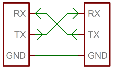
In UART communication, two UARTs communicate directly with each other. The transmitting UART converts parallel data from a controlling device like a CPU into serial form, transmits it in serial to the receiving UART, which then converts the serial data back into parallel data for the receiving device. Only three wires are needed to transmit data between two UARTs. Data flows from the Tx pin of the transmitting UART to the Rx pin of the receiving UART:


How to connect UART serial Device to raspberry PI GPIO ?

Raspberry Pi board TX, RX pin identification has shown below. You can use PIN6 as common ground between raspberry Pi and the STM32.And you need to follow certain steps in order to enable the serial connection .
Make a click on this link and be careful with the instructions .

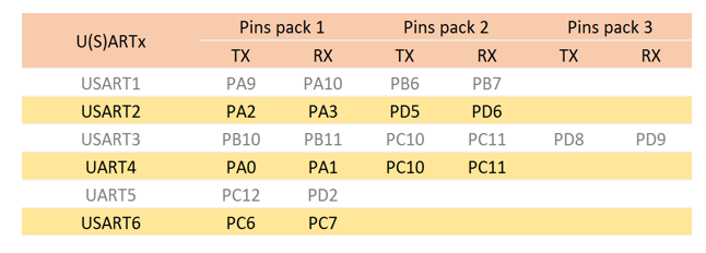
How to connect UART serial Device to STM32F4 pins  ?

STM32F4 Discovery board has 6 U(S)ART channels (USART1, USART2, USART3, UART4, UART5, and USART6). here is a part of the STM32F4 discovery board block diagram. 


USART can be used for communication with PC or another device that use USART communication such as bluetooth module, GSM module and so much more. USART 1 and USART6 are connected to APB2 bus . USART2, USART3, UART4, UART5 are connected to APB1 bus. 


ADC is stands for Analog to Digital Converter. Microcontrollers are digital component, so they only understand discrete/digital signals. Therefore if you want to read analog voltage that can be from various sensors, you need an ADC.
STM32F407 has 3 ADC that can work independently. Every ADC have 18 channels. 16 channels are external and connected to GPIO pin. 2 channels are internal that connected to internal temperature sensor and ADC voltage reference.

When you use ADC, you can choose which ADC and its channel from this table:

LDR (Light Dependent Resistor) is a component that has a (variable) resistance that changes with the light intensity that falls upon it .the relation between light and resistance is decribed  in the graph below .


Before passing by the coding part ,let’s talk about the whole process step by step :

  1. Raspberrypi2 will open the serial port and send a particular message to STM32F4  **The message is “sendthedata”  **
  2. STM32F4 waits for this exact message and prepares its data in a buffer
  3. Once the STM32F4 has received the message , it will send the light’s level each 15 seconds ,If no message has been transmitted by Rpi nothing will be sent.
  4. RPi will read this data and upload it immediatly to the platform “ThingSpeak”

The configuration part under STM32CubeMX:

CubeMX was used mainly to initializing the needed peripherals as ADC 1 and USART 1, also to get the board ready to make such an application by ensuring the clock's configuration throw the HSE.
Also throw CubeMX, we could fix in wich mode exactly our receiving of data must be done (Polling mode, DMA if there is a hardware mapping or a simple UART interrupt). 

The input pin of the LDR is going to be as an ADC input connected to the GPIO pin PA0 of the stm32 board. this one have to be connected or hardware speaking "mapped" to the ADC1 input channel, also it have to be configured as a gpio in analog mode.
You may need to search for the reference manual (RM)  and user manual delivered by the ST Microelectronics to know more about registers , peripherals and the function of all pins.

An ADC (Analog-to-Digital Converter) is a peripheral that allows measuring the voltage (between 0 and Vref) on a certain input of the microcontroller and converting it into a number between 0 and 2N-1 where N is the ADC resolution

For more details about the STM32’s ADC block , those links can help you:


The STM32CubeMX is based on the HAL library .HAL drivers provided from ST for each section.

RCC (Reset and Clock Control) library is needed to set up clocks for running STM devices at high speed. 
For more detailed information look into this link :https://stm32f4-discovery.net/tag/rcc/

After setting up the peripheral , the clock , the adc input pin and the uart pins on STM32CubeMX let’s run it to generate the C code and all necessary files(drivers.h or libraries  ) and let’s add few lines to the main function after declaring new variables:
   
----------------------------------------------------------------------------------
-- Company: 
-- Engineer: Ibtihel Ben Ali
-- 
-- Create Date:    13:17:33 25/08/2018 
-- Design Name: 
-- Module Name:    Cloud_Computing 
-- Project Name: 
-- Target Devices: 
-- Tool versions: 
-- Description: 
--
-- Dependencies: 
--
-- Revision: 
-- Revision 0.01 - File Created
-- Additional Comments: 
--
----------------------------------------------------------------------------------

*declaring the user variables*/
uint8_t data_rx[12];
uint8_t ldr_value;
uint8_t light;
volatile uint16_t adc_value=0;
uint8_t data_tx[1];
int main(void)
{
HAL_Init();
/* Configure the system clock */
SystemClock_Config();
/* Initialize all configured peripherals */
MX_GPIO_Init();
MX_ADC1_Init();
MX_USART1_UART_Init();
/* Infinite loop */
/* USER CODE BEGIN WHILE */
while (1)
{
HAL_ADC_Start(&hadc1);/*Start the ADC peripheral */
HAL_ADC_PollForConversion(&hadc1,100); /*With polling, you're continuously checking to see if conversion is complete */
adc_value=HAL_ADC_GetValue(&hadc1); /*returns a value between 0(0 volts )and 4095(5 volts)*/
ldr_value=(adc_value*5)/4095; /*convert adc values to voltages **/
/*add 48 to each value as an ASCII code */
 light=ldr_value+ '0';
data_tx[0]=light;  
HAL_UART_Receive_IT(&huart1, data_rx, 12); /*transmit the data*/
HAL_UART_Transmit_IT(&huart1, data_tx,1); 
     HAL_Delay(15000);
     }
  /* USER CODE END 3 */
  }


In the code above you can look into the delay , that delay wasn’t random .
I can explain more for you :

the platform « thingspeak » that i’m going to send my data to can only upload data every 15 seconds , if you send any other information or try to do some update try to do it like that at 0s 15s 30s 45s etc .. because it will not detect the correct values it can only accept values in this particular timing .So the raspberry PI is only the bridge between STM32 and thingspeak . this delay must be respected by both stm32 and RPI.
The raspberry pi C code : PART1 (opening the serial port)

#include<stdio.h>
#include<unistd.h> //Used for UART
#include<fcntl.h> //Used for UART
#include<termios.h> //Used for UART
#include<string.h>
#include<stdlib.h>
#include<stdint.h>
#include<curl/curl.h>
int main(intargc , char** argv)
{
        //Setting Up The UART
       //----- SETUP USART 0 -----
        //At bootup, pins 14 and 15 arealready set to UART0_TX, UART0_RX  respectively
                int uart0_filestream = -1;
                //OPEN THE UART
                //The flags (defined infcntl.h):
                //Access modes (use 1 of these):
                //                            O_RDONLY - Open for reading only.
                //                            O_RDWR - Open for reading and writing.
                //                            O_WRONLY - Open for writing only.
                //
                //            O_NDELAY / O_NONBLOCK (same function) - Enables nonblocking mode. When set read requests on the file can return immediately with a failure status
//if there is no input immediately available (instead of blocking). Likewise, write requests can also return
uart0_filestream = open("/dev/ttyAMA0", O_RDWR | O_NOCTTY | O_NDELAY);      
//Open in non blockingread/write mode
 if (uart0_filestream == -1)
{
//ERROR - CAN'T OPEN SERIAL PORT
printf("Error - Unable to open UART.  Ensure it is not in use by another application\n");
}
else
{
printf("port is  opened\n");
}
//The flags (defined in /usr/include/termios.h – see    http://pubs.opengroup.org/onlinepubs/007908799/xsh/termios.h.html)
//            Baud rate:- B1200, B2400, B4800, B9600, B19200, B38400, B57600, B115200, B230400, B460800, B500000, B576000, B921600, B1000000, B1152000, B1500000, B2000000, B2500000, B3000000, B3500000, B4000000
                //            CSIZE:- CS5, CS6, CS7, CS8
                //            CLOCAL - Ignore modem status lines
                //            CREAD - Enable receiver
                //            IGNPAR = Ignore characters with parity errors
            //            ICRNL - Map CR to NL on input (Use for ASCII comms where you want to auto correct end of line characters - don't use for bianry comms!)
                //            PARENB - Parity enable
                //            PARODD - Odd parity (else even)
struct termios options;
tcgetattr(uart0_filestream,&options);
options.c_cflag = B115200 | CS8 | CLOCAL | CREAD;//Set the same baud rate as with stm32
options.c_iflag = IGNPAR;
options.c_oflag = 0;
options.c_lflag = 0;
tcflush(uart0_filestream,TCIFLUSH);
tcsetattr(uart0_filestream,TCSANOW, &options);
while(1){
             *p_tx_buffer++ ='s';
             *p_tx_buffer++ ='e';
             *p_tx_buffer++ ='n';
             *p_tx_buffer++ ='d';
             *p_tx_buffer++ ='t';
             *p_tx_buffer++ = 'h';
             *p_tx_buffer++ = 'e';
             *p_tx_buffer++ = 'd';
             *p_tx_buffer++ = 'a';
             *p_tx_buffer++ = 't';
             *p_tx_buffer++ = 'a';
             *p_tx_buffer++ ='\0';
                if(uart0_filestream != -1)
                {
 int count = write(uart0_filestream, tx_buffer, 12);     
               //Filestream, bytes to write, number of bytes to write
                               if (count < 0)
                               {
                                               printf("UART TX error\n");
                               }
                           else
                            {
                              printf("the trasmitted message to GPIO15/RPI is %s \n",tx_buffer);
                            }
                }
After running the code in both sides you will see on the IAR EW watch option this little table :

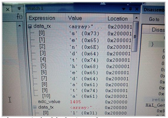
The message have been received and the data is set to be sent .

PART 3 : receiving the data and uploading it at the same time


CURL *curl;
CURLcode res;
char url [67] = "https://api.thingspeak.com/update?api_key=KFLBHCXC9A4J2P2E&field1=";
char rx_buffer[1];
int rx_length = read(uart0_filestream,rx_buffer, 1);
               if (uart0_filestream != -1)
                {
                               if (rx_length < 0)
                               {
                               }
                               else if (rx_length == 0)
                               {
printf("no data is coming\n\r ");
                             }
                              else
                             {
rx_buffer[rx_length] = '\0';
printf("%i byte received from GPIO14/stm32\n" , rx_length);                        
printf(" data received %s\n",rx_buffer);
curl_global_init(CURL_GLOBAL_ALL);
url [66] =rx_buffer[0];
 curl = curl_easy_init();
curl_easy_setopt(curl,CURLOPT_URL,url);               
res = curl_easy_perform(curl);
if(res!= CURLE_OK)
system("echo 6");
fprintf(stderr, "curl_easy_perform() failed: %s\n");                     
curl_easy_cleanup(curl);       
curl_global_cleanup();
               }
        }
   sleep(15);
  }
close (uart0_filestream);
return 0;
}
To run the C code on raspberry pi use this command line gcc –o Project Project.c –lcurl
This is how my terminal looks like :

PART5 : i have already created an account on thingspeak now all i have is to prepare my channel and my field for my data :


We are so grateful to our future engineer Ibtihel BEN ALI for such an amazing article. 
For more information:


Hope you enjoy it : #the_future_is_bright

dimanche 8 juillet 2018

STM32 For beginer, all in one package.

STM32 For beginer, all in one package.

Hello, you will find here a full cracked copy of IAR EWARM warkbench, STM32F3 & F4 cube containing all needed exemples, drivers and demonstrations to develop your one application using STM32 MCU.
Good Luck.


dimanche 1 avril 2018

PodoSave

What is PodoSave ? PodoSave : My new project developed in partnership with Enactus Tunis, it is about a smart wearable soles made using bluetooth and a lot of sensors working together under a low power consumption, able to detect, collect and store in real time the movements, the sensibility and the entourage on the diabetic feet such as pressure, temperature, humidity.


The prototype has been developed, tried successfully on several diabetics feet and today chosen as second best project by the Islamic Development Banc.


#Follow your Feet
#Evoid Diabetic feet issues & injuries.
#PodoSave.

lundi 12 décembre 2016

Digital Decimation Filter Using FPGA Board.

Our task is to describe in VHDL, Test, and implement a DSP circuit called Decimation Filter. This one has two main sections: the CIC section and the FIR section.
Even the CIC and the FIR filters are composed of many sections thats we are going to describe them one by one.
Both sections consist of N stages each. The exact structure of each stage, and the way of connecting all stages together are presented below in this article today.


So let's start by introducing a Decimation filter.
A Decimation Filter is one of the most used filters in signal processing and noise avoiding sustems.

Basically a decimator is a digital low pass filter, which also include the operation of sample rate reduction. He does operation of noise shaping and hence the noise is pushed to higher frequencies so that the decimation stage following the modulator can filter out this noise above the cutoff frequency.

The band limited signal can then be resampled by discarding X – 1 samples out of every X samples, where X being the oversampling ratio. By averaging X samples out of the quantized sigma-delta output.
The decimation filter achieves a high output resolution and also the frequency of the output data is at twice the input signal bandwidth which is the nyquist rate.
So to concluse how decimator filter work:

This is our input signal X(n):

   
We want to decimate this signal wiith decimation ratio R = 2.
This means thats we are going to generate a Y(n) decimation response of X(n) with the half frequency of X(n) = 0.5 Hz.

In digital signal processing, decimation is the process of reducing the sampling rate of a signal. Complementary to interpolation, which increases sampling rate, it is a specific case of sample rate conversion in a multi-rate digital signal processing system. Decimation utilises filtering to mitigate aliasing distortion, which can occur when simply downsampling a signal. A system component that performs decimation is called a decimator.

So Decimation filter is a low pass filter able to decrease sampling rate, it is composed by mixing a CIC Filter with a Fir Filter.

Cascaded integrator–comb filter :CIC Filter

A CIC filter consists of one or more integrator and comb filter pairs. In the case of a decimating CIC, the input signal is fed through one or more cascaded integrators, then a down-sampler, followed by one or more comb sections (equal in number to the number of integrators). An interpolating CIC is simply the reverse of this architecture, with the down-sampler replaced with a zero-stuffer (up-sampler).

{\begin{aligned}H(z)&=\left[\sum _{{k=0}}^{{RM-1}}z^{{-k}}\right]^{N}\\&=\left({\frac  {1-z^{{-RM}}}{1-z^{{-1}}}}\right)^{N}\end{aligned}}
Where:
R = decimation or interpolation ratio
M = number of samples per stage (usually 1 but sometimes 2)
N = number of stages in filter
Characteristics of CIC Filters
  1. Linear phase response;
  2. Utilize only delay and addition and subtraction; that is, it requires no multiplication operations

CIC Filter is composed by mixing integrators,comb blocks with frequency dividers.

Integrator:

A digital integrator block is a block who add the previous result with present input to generate present output so simply :
  Y(n) = Y(n-1) + X(n) 


To create this block in VHDL, you have to use an intelligent way in program who help you to control your input signal delayed and to avoid critical value who could generate incorrect result specially when we look for Y(0).

Comb:

 The principal function of a comb filter is mixing a delayed version of a signal to itself.

Y(n) = X(n) + X(n-RM)

When both R and M are positive constants:


CIC Filter is like i said before a collection of Integrator Filter equal to a collection of a Comb Filter when Integrators work inside a simple frequency and Comb Filters work inside the same frequency divided by the decimation ratio.


Here is the global RTL of our CIC filter:


We cant talk about CIC filter without mentioned a block named Frequency divider, this one is a generator of clock slower thant our initial clock.
In fact, he is no more than a simple circuit based on a simple  front counter.


Exactly like this Test bench here explain for every 4 initial clock (Red signal) we generate one clock slower edge(blue signal).

To build your own CIC Filter, all what you have to do is to :
  1.  Chose N : Filter ordre, (4 in my exemple)
  2.  Select R : Decimation ratio. (4 in my exemple)
  3.  Build your Integrator stages. 
  4.  Build your Comb stages.
  5.  Build your frequency Divider block.
  6.  build the top level CIC_Filter mapping all those blocks together.


Finite Impulse Response  :FIR Filter

Wikipedia define Fir Filter as a filter whose impulse response (or response to any finite length input) is of finite duration, because it settles to zero in finite time. This is in contrast to infinite impulse response (IIR) filters, which may have internal feedback and may continue to respond indefinitely (usually decaying).
The impulse response (that is, the output in response to a Kronecker delta input) of an Nth-order discrete-time FIR filter lasts exactly N + 1 samples (from first nonzero element through last nonzero element) before it then settles to zero.
FIR filters can be discrete-time or continuous-time, and digital or analog.  

We could simply define it as a low pass filter made using convolution of the inputs signals with their impulse response.

fir_filter_equation

where:
  • x[n] is the input signal,
  • y[n] is the output signal,
  • N is the filter order; a Nth-order filter has (N+1) terms on the right-hand side
  • bi is the value of the impulse response at the i’th instant for 0<= i <=N of a Nth-order FIR filter. If the filter is a direct form FIR filter then is also a coefficient of the filter 

So to implement this filter using VHDL all what you have to do is to follow this architecture here :


In your program you have to use an array when you will put inside it your inputs signals delayed to facilate program algorithme.


A simple test bench of our Fir filter give:


We could verify results value by putting somes inputs signals inside a Fir block in Labview or Matlab simulink and comparing it together.

Decimation Filter:

Now after bulding the CIC Filter and the FIR we have just to connect them together to have the final decimation filter.
Here is the top Level RTL of the global Work.


___________
___________


After bulding and mapping all those blocks together a final test bench give 


Top Level VHDL Code is :

----------------------------------------------------------------------------------
-- Company: 
-- Engineer: 
-- 
-- Create Date:    13:17:33 12/11/2016 
-- Design Name: 
-- Module Name:    Decimation_filter - Behavioral 
-- Project Name: 
-- Target Devices: 
-- Tool versions: 
-- Description: 
--
-- Dependencies: 
--
-- Revision: 
-- Revision 0.01 - File Created
-- Additional Comments: 
--
----------------------------------------------------------------------------------
library IEEE;
use IEEE.STD_LOGIC_1164.ALL;

-- Uncomment the following library declaration if using
-- arithmetic functions with Signed or Unsigned values
--use IEEE.NUMERIC_STD.ALL;

-- Uncomment the following library declaration if instantiating
-- any Xilinx primitives in this code.
--library UNISIM;
--use UNISIM.VComponents.all;

entity Decimation_filter is
    Port ( Xin : in  STD_LOGIC_VECTOR (7 downto 0);
           Yout : out  STD_LOGIC_VECTOR (7 downto 0);
           clk : in  STD_LOGIC;
     h0: in std_logic_vector(7 downto 0);
     h1: in std_logic_vector(7 downto 0);
     h2: in std_logic_vector(7 downto 0);
     h3: in std_logic_vector(7 downto 0);
           rst : in  STD_LOGIC);
end Decimation_filter;

architecture Behavioral of Decimation_filter is
component FIR port 
(clk: in std_logic;
rst: in std_logic;
x: in std_logic_vector(7 downto 0);
h0: in std_logic_vector(7 downto 0);
h1: in std_logic_vector(7 downto 0);
h2: in std_logic_vector(7 downto 0);
h3: in std_logic_vector(7 downto 0);
y: out std_logic_vector(7 downto 0));
end component;
component comb2 port 
(rst : in  STD_LOGIC;
           clk : in  STD_LOGIC;
           x : in  STD_LOGIC_VECTOR (10 downto 0);
           y : out  STD_LOGIC_VECTOR (9 downto 0));
end component;
component comb3 port 
(rst : in  STD_LOGIC;
           clk : in  STD_LOGIC;
           x : in  STD_LOGIC_VECTOR (9 downto 0);
           y : out  STD_LOGIC_VECTOR (8 downto 0));
end component;
component comb4 port 
(rst : in  STD_LOGIC;
           clk : in  STD_LOGIC;
           x : in  STD_LOGIC_VECTOR (8 downto 0);
           y : out  STD_LOGIC_VECTOR (7 downto 0));
end component;
component comb port 
(rst : in  STD_LOGIC;
           clk : in  STD_LOGIC;
           x : in  STD_LOGIC_VECTOR (11 downto 0);
           y : out  STD_LOGIC_VECTOR (10 downto 0));
end component;
component first_integrator port 
(clk : in  STD_LOGIC;
           rst : in  STD_LOGIC;
           x : in  STD_LOGIC_VECTOR (7 downto 0);
           y : out  STD_LOGIC_VECTOR (8 downto 0));
end component;
component second_integrator port 
(x : in  STD_LOGIC_VECTOR (8 downto 0);
           y : out  STD_LOGIC_VECTOR (9 downto 0);
           clk : in  STD_LOGIC;
           rst : in  STD_LOGIC);
end component;
component third_integrator port 
(clk : in  STD_LOGIC;
           rst : in  STD_LOGIC;
           x : in  STD_LOGIC_VECTOR (9 downto 0);
           y : out  STD_LOGIC_VECTOR (10 downto 0));
end component;
component last_integrator port 
(clk : in  STD_LOGIC;
           rst : in  STD_LOGIC;
           x : in  STD_LOGIC_VECTOR (10 downto 0);
           y : out  STD_LOGIC_VECTOR (11 downto 0));
end component;
component frequency_divider port 
(clk : in  STD_LOGIC;
           rst : in  STD_LOGIC;
           clk_out : out  STD_LOGIC);
end component;


signal aymen1 : std_logic_vector(0 to 8);
signal aymen2 : std_logic_vector(0 to 9);
signal aymen3 : std_logic_vector(0 to 10);
signal aymen4 : std_logic_vector(0 to 11);
signal aymen5 : std_logic;
signal aymen6 : std_logic_vector(0 to 10);
signal aymen7 : std_logic_vector(0 to 9);
signal aymen8 : std_logic_vector(0 to 8);
signal aymen9 : std_logic_vector(0 to 7);
begin
v1:first_integrator port map (clk,rst,Xin,aymen1);
v2:second_integrator port map (aymen1,aymen2,clk,rst);
v3:third_integrator port map (clk,rst,aymen2,aymen3);
v4:last_integrator port map (clk,rst,aymen3,aymen4);
v5:frequency_divider port map (clk,rst,aymen5);
v6:comb port map (rst,aymen5,aymen4,aymen6);
v7:comb2 port map (rst,aymen5,aymen6,aymen7);
v8:comb3 port map (rst,aymen5,aymen7,aymen8);
v9:comb4 port map (rst,aymen5,aymen8,aymen9);
v10:FIR port map (aymen5,rst,aymen9,h0,h1,h2,h3,Yout);
end Behavioral;


If you want to have a copy of any block vhdl code just contact me, Just contact me.
                                                                   

                                                           See you Soon AYMEN LACHKHEM